10.3. Energy Storage#
In the previous two chapters, we reviewed wind power and solar power generation and found that in both cases there is considerable intermittency in the supply of the power to drive the turbines or photovoltaic cells. The wind power is extremely volatile in that it fluctuates on the time scale of days, associated with diurnal heat fluctuations, weeks associated with weather patterns, and seasonally, while the solar radiation has both regular diurnal and seasonal cycles and then irregular intermittency associated with cloud cover or pollutants in the atmosphere.
In developing a reliable energy system, with continuous power supply, this intermittency needs to be buffered and if we are to use carbon free solutions rather than the gas fired power stations which buffer the system today, we need a system which can replace the renewable supply at short hourly timescales, associated with weather and diurnal cycles, and also on seasonal time scales.
Given the lack of an alternative energy source which can ramp up and ramp down at the high frequency of the diurnal fluctuations we have seen, there is a need for energy storage which has a rapid response, and which will enable long term storage. Fig. 10.22 illustrates that different technical solutions for energy storage have different time constants for storing the energy and also in terms of the total amount of energy they can store: flywheels and batteries have a relatively short time scales over which they remain charged, and relative small energy capacity. Hydrogen stored in large salt caverns and water pumped up to power hydroelectric turbines have relatively large total amounts of energy they can store. These solutions can store the energy for a long time, rather than discharging on times of days to weeks.
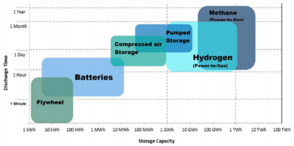
Fig. 10.22 Available storage technologies, their capacity and discharge time (School of Engineering, RMIT University, 2015).#
In developing a reliable electricity supply, in addition to storage solutions, there is also the option of building oversupply. This can be compared with building storage and from the two taken in conjuction an optimum solution emerges. Our initial interest here is to explore the types of storage available and to consider their materiality and energy efficiency. Many of the solutions involve interaction with the environment in some way, given the scale of the systems needed. The nature of these interactions will emerge from the discussion.
Battery storage#
Batteries such as lithium ion, or more recent calcium ion batteries, are likely to have a major role in short term storage to help buffer short term intermittency, and systems to achieve this are already being developed (e.g. Kaui in Hawaii). Battery technology is well developed from their application in electric vehicles, and many of the new battery systems can accommodate multiple charge-recharge cycles as would be needed in an energy storage system. There are some limitations to the potential scale-up of battery storage however, including extraction of the raw materials for the batteries.
Batteries are likely to provide local solutions for short term intermittency, and provide a means to decentralise the grid. However, they are not suitable for longer term storage owing to the finite charge retention time, or to very large scale energy storage, given the sheer numbers of batteries which would be needed.
For example, in the UK, the present electricity supply is of order 40 GW. For one hour of storage using 100 kWhr batteries, comparable to those in the Tesla vehicle, we would need 400,000 such batteries. If we extended this to 1 weeks storage, which represents about 175 hours, we would require about 62 million such batteries dedicated to the energy storage system.
Pumped hydro-power & centrifuge systems#
An alternative short term energy storage system may emerge from the addition of new hydrostorage on the Dinorwig reservoir in Wales, which has been operational for several decades. This system pumps water from low level to a higher level reservoir, and then allows this to discharge when required.
The Dinorwig system then converts potential energy to power, by allowing the reservoir to drain rapidly. The drainage drives 6 turbines which generate 1800 MW and overall there is a power capacity of about 9 GWhrs. The flow rate is about 390 m^3^/s!
As an idealisation, if we assume no frictional losses as the water flows downslope to the turbine, the water entering the turbine may release its potential energy \(ρgh\) and with volume flow rate \(Q\), then the rate of doing work is \(Qρgh\). To develop power of 1800 MW, this implies a change in height of about 600 m, which is similar to the change in height at Dinorwig. After discharge, the water is pumped back to the upper reservoir. In practice, the round trip has an efficiency of about 75% in terms of power recaptured.
More such systems can be developed for rapid response short term energy management, but the total capacity of 9 GWhrs illustrates the scale of new development for more storage; at present this would provide 1.8 GW to the UK grid for 4-5 hours. There are some new sites for such developments, but this will only be part of the solution given the present power supply of about 40 GW.
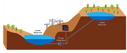
Fig. 10.23 Cartoon schematic of a hydro-electric energy storage facility.#

Fig. 10.24 Dinorwig hydro-electric power station reservoir.#
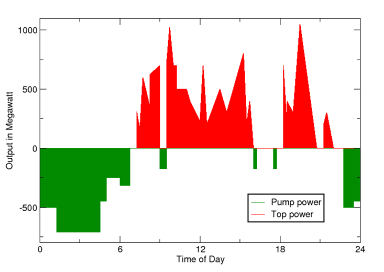
Fig. 10.25 Power over the course of a day for the storage and release of energy from a hydro-pumped storage.#
Flywheels#
Large rotating flywheels can store energy, but they gradually dissipate this energy owing to the friction or drag. There is also a limit on the scale of flywheels in terms of the strength of the materials. If we consider a disk, of radius \(R\), thickness \(h\), density \(\rho\), rotating with angular frequency \(\omega\), then the rotational energy is
Typical flywheels may have 50 kWh storage and can respond very rapidly; for example, slowing the wheel over 15 minutes leads to 200 kW power. Flywheel storage systems may involve multiple wheels to provide large amounts of power for short times to help balance the short term intermittency in the supply. The strength of the material eventually limits the rotation rate or size of the wheel.
Compressed air in salt caverns & aquifers#
The storage of a large volume of compressed air provides another means of very large scale energy storage. There is a notable example in Huntdorf in Germany, where a salt cavern of size 300,000 m3 can store air up to pressures of 100 atmospheres (107 Pa). The air is pumped into the cavern when there is excess or cheap energy and the energy is returned to the surface when the demand is high: on reaching the surface the air passes through a turbine and generates power. There have been some developments of the engineering design of these systems to ensure they are as efficient thermodynamically as possible, owing to the heating during compression of the air, and the heat and other energy losses from the system. In the context of a renewable energy system, such compressed air storage can help buffer the short term intermittency in the supply, and the power generated from the cavern may be very substantial, comparable to the pumped hydro-storage solution.
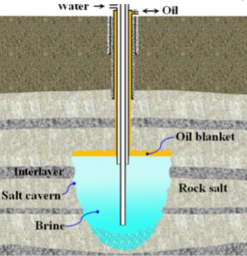
Fig. 10.26 Schematic of a salt cavern.#
For example, if a mass of air \(m\) is stored at temperature \(T\) and at a pressure \(P\) in a cavern then we know that
where \(R\) is the air gas constant, \(R =\) 461 J/kg/K and \(\rho\) is the density. Also, the mass of air is related to the volume of the cavern by
and the internal energy of this compressed air is
Combining these relations we find
With \(c_v\) = 1000 J/kg/K and a pressure of 107 Pa, a cavern of volume \(V\) = 106 m3 will have air with internal energy \(E\) = 3 × 10¹³ J ~ 106 kWh
Hence the cavern can store about 1 GWhr of energy. Not all of this can be recovered owing to inefficiencies in the system, but with an efficiency of 50-60%, this would still be a significant storage. The air can be released from such a system very rapidly so the power out may be of order 0.2-0.3 GW and will persist for 1-2 hours. One key factor is that on compressing the air for injection underground, the temperature of the air typically increases considerably, with the adiabatic increase in temperature being given by the law
Often some of this thermal energy is removed from the air prior to injection in the ground, and stored at the surface, for example in a water reservoir. On extraction of the gas from the subsurface, the air tends to cool down as the pressure falls again, but there will be a minimum temperature of air which can pass through the turbine to generate electricity. In order to reduce this cooling, the stored thermal energy is then used to partially reheat the air.
With a growing mass of renewables, compressed air storage could be very important. As simple order of magnitude calculations, 100 caverns would lead to about 20 GW power generation for 1-2 hours assuming certain efficiency of storage. If we needed this level of power for 12 days, we would need about 1200 such caverns for the UK (order of magnitude).
Fig. 10.27 illustrates the locations where there are gas storage sites and also where there are salt deposits, illustrating that there is plenty of salt, at least in some regions, to allow development of such caverns.
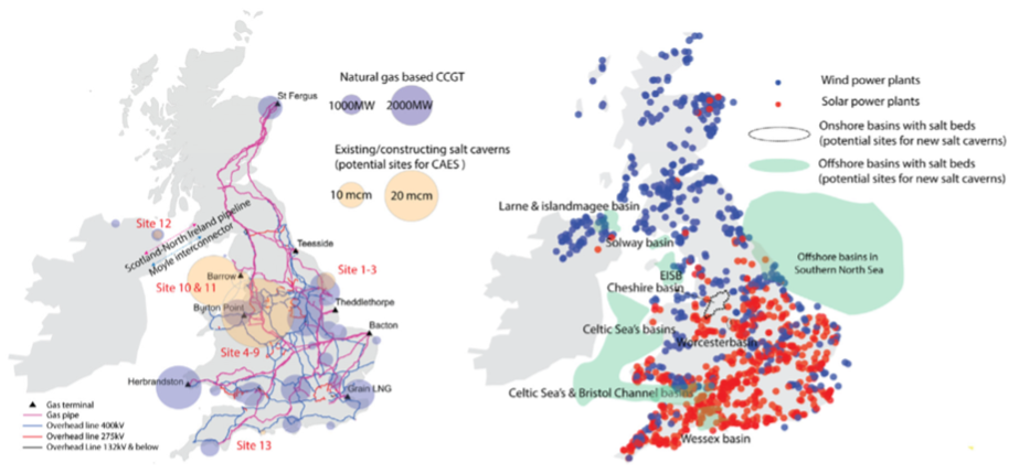
Fig. 10.27 Gas power, solar, and wind generation and existing and potential underground gas storage facilities in the UK. Left shows the existing gas power and underground storage facilities. Right shows the geological resources for underground gas storage and current solar and wind generation.#
It is also possible to store compressed air in an aquifer, and this provides a larger volume in which to pump the air. In order to achieve this, the aquifer needs to have a structural trap of some form the keep the air localised so it can be recovered, as in the case of an anticline shown in Fig. 10.28.
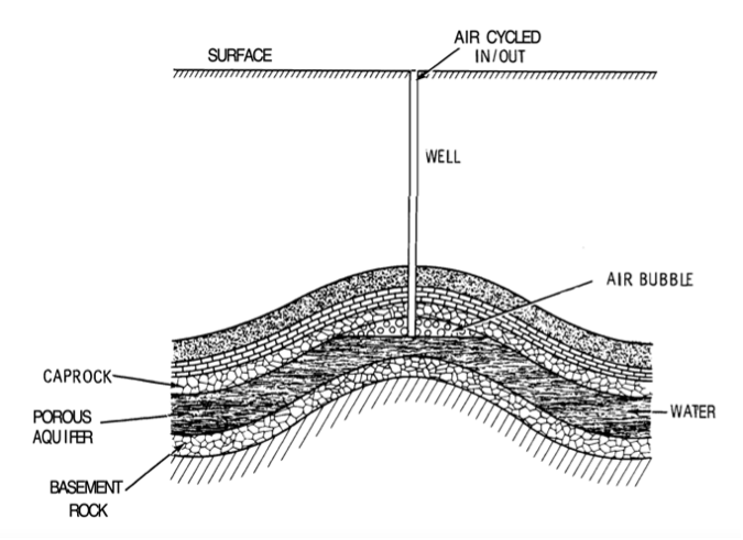
Fig. 10.28 An aquifer structure that could be used for air storage.#
If the aquifer is axisymmetric, and extends a radial distance \(r\) = 3km and is \(h\) = 20 m thick, this represents a volume of
If the permeable layer of rock has porosity 0.2, then the pore volume available is about
One could thus try to store about 100 times more air in such an aquifer that a salt cavern, and with a comparable recovery flow rate of the compressed air to the surface, this would provide a power source for several days during times of low renewable energy generation.
One challenge with air storage in an aquifer is the tendency of the air-water interface to become unstable; the air develops fingers which advance into the water zone along particular pathways. As a result of the instability, some of the air becomes trapped in the water zone and is hard to extract owing to capillary forces. This instability arises in two different regimes as the air is displacing the water. To understand the instability we need to consider two different limits. First, the flow of the air through the porous media may be controlled by either
the viscous dissipation of the air as it migrates through the pores, according to Darcys law
the capillary pressure at the air-water interface which tends to suppress the migration of air into successive pore spaces, owing to the narrow pore throats separating the pore spaces.
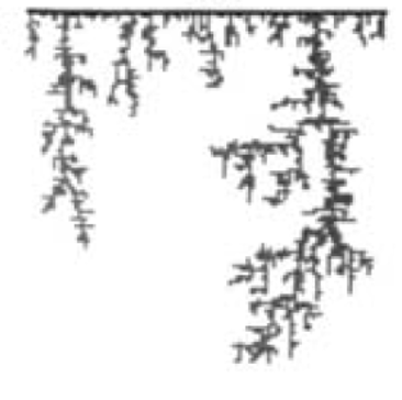
In the first case, the pressure gradient in the air is smaller than the pressure gradient in the water-filled region further from the well. As a result it is easier for the advancing air to develop channels or fingers through the water rather than displacing the relatively viscous water. This leads to the viscous fingers shown in the Fig. 10.29 below (after Beeson-Jones and Woods, 2019 and Lenormand and Zircone, 1989).
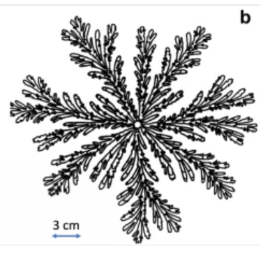
Fig. 10.29 Figure structures that can develope at the air-water interface.#
In the second case, the capillary pressure jump across the air-water interface dominates the pressure change through the system. As the interface tries to advance through the small pore spaces, it needs to deform and the radius of curvature becomes smaller - this leads to a large pressure jump across the interface, which in a rock is different across each pore-throat. As a result, the interface advances as a percolation type process, with the interface breaking through the larger pore spaces which need less deformation of the interface. The interface then seeks out the next easiest pore-space to migrate across, and this leads to the development of an irregular, capillary-fingered interface.
In an attempt to overcome this challenge, it has been proposed to injected a buffer zone of air can be injected into the aquifer, known as the cushion gas, and this separates the air which is injected and extracted from the water located further from the well (see Fig. 10.28).
Hydrogen Storage#
A further energy storage system which is gaining significant traction is hydrogen. At present there is an enormous demand for hydrogen as a feedstock in industry, with nearly 100 Mt being produced annually across the globe. At present this is primarily produced through the steam reformation of methane, which involves mixing vapour and methane and heating it to 700C or higher. The hydrogen and CO2 separate during this process, and it is then possible to capture the CO2 and store this geologically (see carbon storage lecture), leading to what is called blue hydrogen. However, as the supply of renewable energy increases, a progressively larger fraction of this hydrogen will be generated using electrolysis, powered by renewable energy, leading to what is referred to as green hydrogen.
Since hydrogen can either be used as the fuel for a hydrogen fuel cell leading to the production of electricity, or hydrogen can be directly combusted to generate heat, and thereby steam which drives a generator to produce electricity, there is a new potential use for hydrogen as a means of energy storage for renewable electricity. The challenge with using hydrogen is that the initial production of hydrogen through electrolysis involves some loss of energy, with the process only being 75-80% efficient, the subsequent compression of the hydrogen leads to a further loss depending on the efficiency of the compression and storage, and the use of hydrogen in a fuel cell leads to about 30% further losses. Work continues to try to reduce these losses, but the round-trip efficiency of electricity conversion to hydrogen and back to electricity may be about 40%. The precise value depends on the detailed system being used. Nonetheless, hydrogen offers an attractive means to store a relatively high energy density material.
The energy density of hydrogen is about \(E_f\) = 34 kWh/kg. This is very high compared to many hydrocarbons on a mass basis, as in the chart below, however, the density of hydrogen is very low.
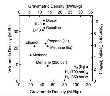
Fig. 10.30 Volumetric and gravimetric density of various fuel sources.#
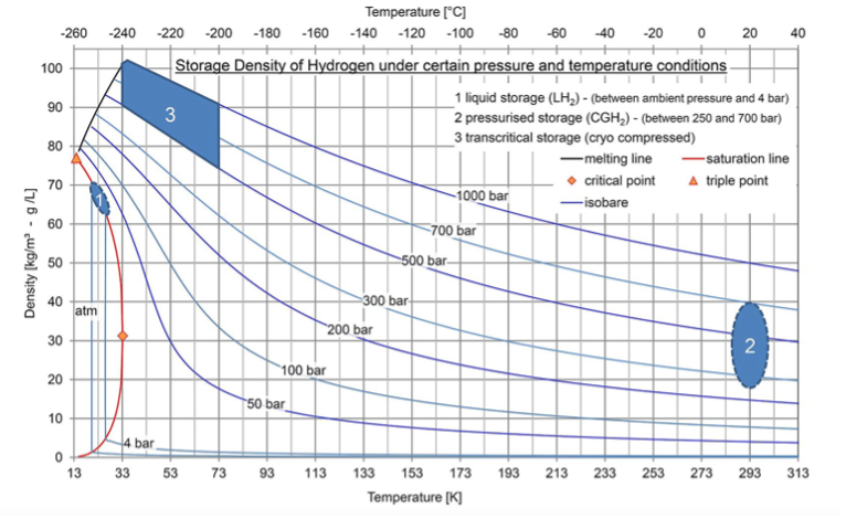
Fig. 10.31 Density of hydrogen as a function of pressure and temperature.#
As an example, if we wanted to store hydrogen in a salt cavern, with volume \(V\) = 105 m3 and at a pressure of \(P\) = 107 Pa ( = 100 bar), then the hydrogen would have a density of order about \(\rho\) = 10 kg/m3 (see chart above) and so we would be able to store \(M = \rho V\) = 106 kg, with a chemical energy of \(E \approx M E_f\) = 3 × 10⁷ kW hrs ~ 30 GWh.
If we wanted to store the capacity to generate 30 GW electricity for 10 days in the event of intermittent renewable supply being absent for 10 days, then given the inefficiency of the conversion of hydrogen to electricity, this would require about 400-500 such caverns since 10 days represents about 240 hours, and the process of electricity generation from hydrogen is not 100% efficient. Again, the earlier map illustrates the potential to develop this number of caverns in the UK for energy storage.
There is also interest in the storage of hydrogen in aquifers, which have a larger volume, as illustrated above in the context of compressed air storage. By analogy with the compressed air storage, the injection of hydrogen into a saline aquifer will displace the ambient water and fill the pore space near the injection site. Presently there is a considerable research effort to understand some of the challenges of such storage in the subsurface.