10.4. Carbon Removal and Storage#
The IPCC have produced a series of scenarios going forward which are designed to help remain within the 1.5-2.0 degree target for global warming. In the majority of these scenarios, there is a key role for carbon removal from the atmosphere. This can be achieved, for example, by capturing carbon released from the burning of biomass for power generation. Such a scheme has been planned at the DRAX power station in northern England; this is a major power station producing 7% of the UK’s power at present. In addition, there are several industrial processes which are hard to decarbonise, including the production of cement and of iron and steel, which produce several percent of global carbon emissions, and which are hard to decarbonise. Cement especially is difficult to decarbonise, as there is a significant emission of CO2 associated with the chemistry of cement production.
By accounting for the CO2 already emitted, plus the likely additional CO2 emissions in the next two decades or so, while the energy transition is being developed, and renewable generation gradually displaces fossil fuels, the IPCC and the IEA suggest in their scenarios of net zero by 2050 that there will be a need to store about 7-8 Gt of CO2 per annum. This is a very significant mass, representing a fraction of about 0.2 of the present global fossil emissions. Presently the world stores about 40 Mt CO2, so there is a scale up by a factor of 200 needed by 2050.
The process of carbon capture is energy intensive, but already established in industry, and while there are technological developments to reduce the costs and energy involved, there are commercial plant which can be built for this. Essentially, in one process, the waste gas stream containing CO2 is passed through a separator tower containing amines into which the CO2 dissolves. The remaining gases can be vented while the amine is then heated up to release the pure stream of CO2.
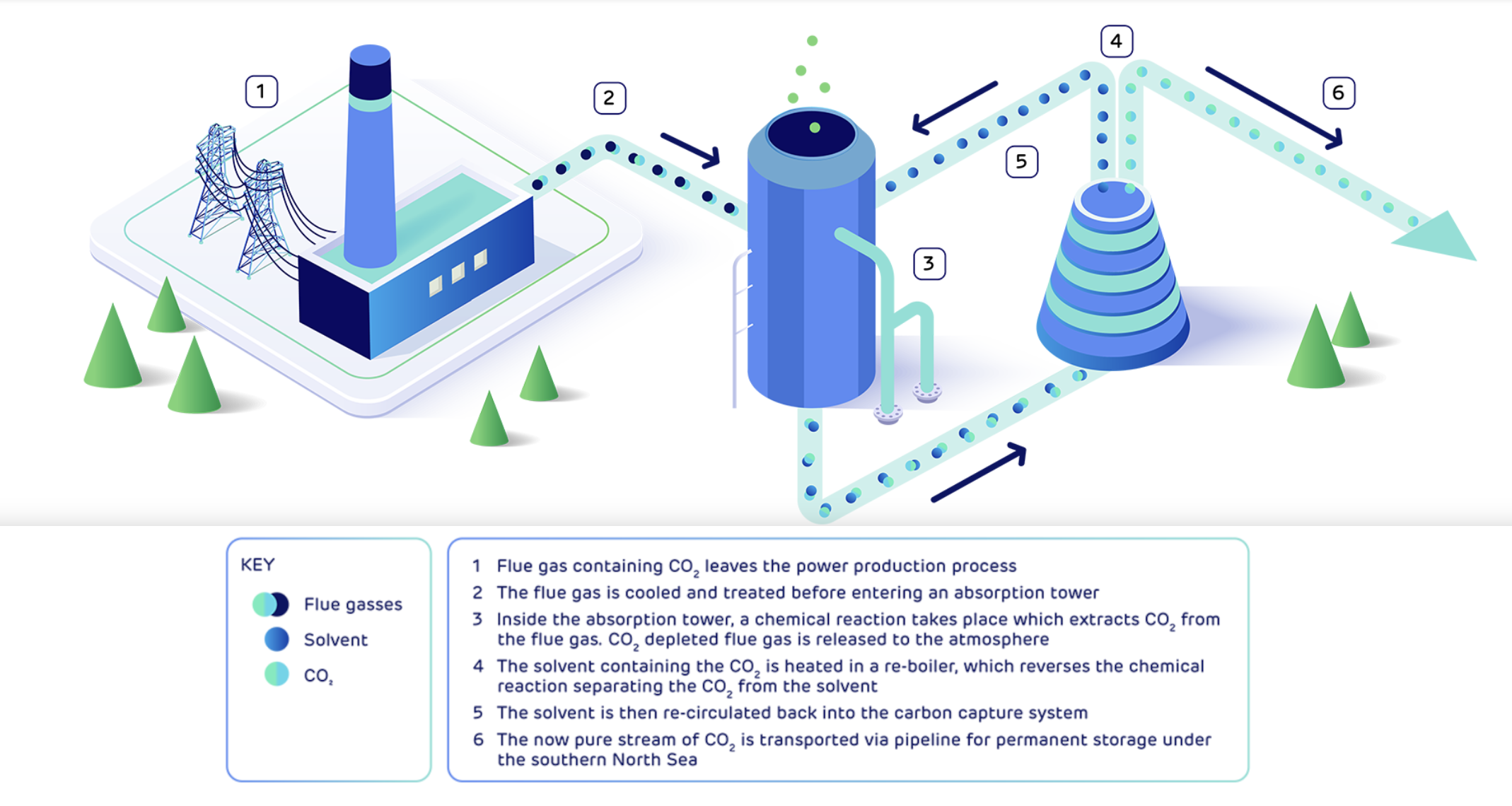
Fig. 10.32 A schematic of Carbon Capture and Storage from DRAX.#
The CO2 is then taken at high pressure along a pipeline or ship to a storage site for injection and geological storage in a deep saline aquifer or depleted oil or gas field, as depths of about 1.5-2.5km below the surface. The timescale over which the storage should be secure is in excess of 1000-10,000 years.
The reason for injecting to these depths is that the CO2 density increases with pressure, and so much more mass of CO2 can be stored per unit volume of rock. Also at these depths the CO2 becomes supercritical, which means that there is no distinction between the liquid and gas phases, but the CO2 is essentially a low viscosity fluid with density in the approximate range of 500-900 kg m-2 depending on the pressure and temperature (see Fig. 10.33).
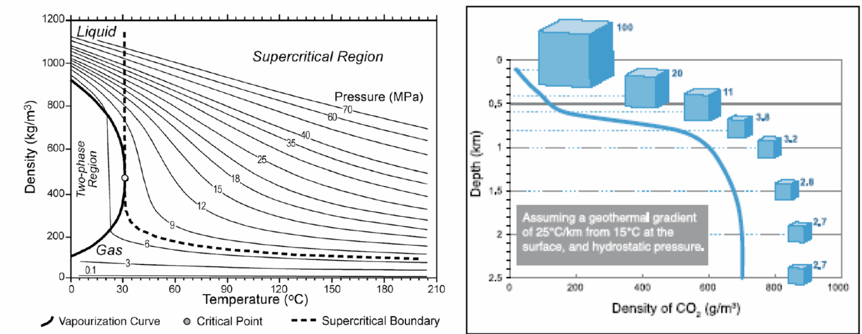
Fig. 10.33 From IPCC 2005.#
On injection into a permeable rock the CO2 spreads through the pore spaces between the grains which make up the solid matrix, typically sandstone in sedimentary rocks. Since many of these rocks are preferentially wetting to water, the CO2 tends to migrate through the centre of the pore spaces leaving a film of water on the solid surface of the grains.
In storing CO2 in the subsurface, one of the key properties which we need to know is the fate of the CO2 over the storage time in the aquifer, and in particular what is the process of trapping the CO2 in the sub-surface. There are four main types of trapping of the CO2.
Structural trapping#
Structural trapping, occurs when buoyant CO2 accumulates below a seal rock layer, for example in an anticline, and so cannot move. We can estimate the time over which a plume accumulates in an anticline from an injection well with a simple calculation. We assume there is a line well of length \(L\) and an injection volume rate \(Q\), and that CO2 issuing from this well rises up towards the top of the anticline.
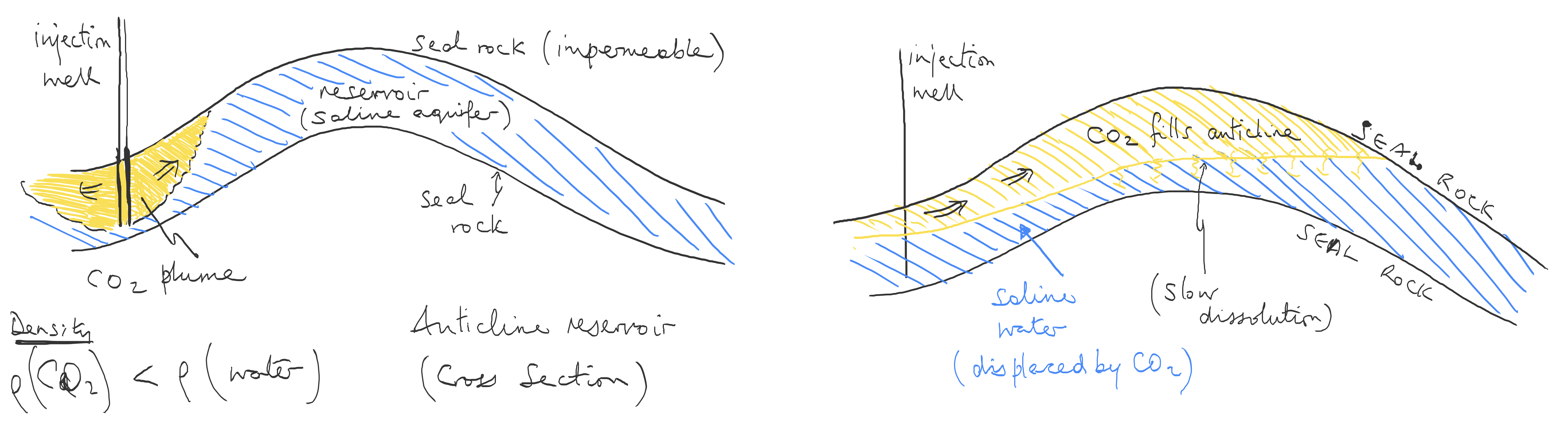
Fig. 10.34 The sub-surface structure of CO2 trapping.#
The speed of the plume depends on the buoyancy force according to Darcy’s law
where \(\Delta \rho\) is the density difference between the CO2 and the water, \(k\) the permeability of the formation, and \(\mu_c\) is the viscosity of the CO2. The plume rising from the well in steady state carries this volume flux up into the anticline so that
where \(h\) is the depth of the plume. In a typical case, we expect to inject about 0.001-0.01 m3 s-1 into the well. If the permeability is 10-13 m2 and the density difference is 100-200 kg/m3, and the viscosity is 0.0001 Pa s, then the plume will have a speed of about 10-6 m/s, and a depth of about 10m as it rises up into the anticline.
Darcy’s law gives us the flux of CO2 per unit area of the rock, but the CO2 only moves through the pore spaces. If the porosity is \(f\), then the actual speed of the fluid is \(u/f\) which would be about 0.5×10⁻⁵ m/s in the present case. In 1 year, (3×10⁷ s) the CO2 will therefore migrate a distance 150m, and so over a period of 10 years, a large anticline, of cross-anticline extent 1km will gradually fill up.
Capillary trapping.#
At the end of the injection, any plume of CO2 in a sloping formation will run upslope, and since there is no more injection of CO2, a trailing edge of the CO2 plume will develop and move upslope. As this moves upslope, water follows the CO2 and tries to fill the pore spaces vacated by the CO2. Since the water is typically the wetting phase, it will move along the surface of the grains in the porous layer, gradually trying to fill in the interior of the pore spaces. As it migrates round the grains, it will tend to surround the CO2 in the pore spaces, between the pore throats in the formation.
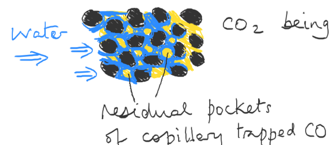
Fig. 10.35 Capillary trapping of CO2 in the pore spaces of a rock.#
This leads to pinch off of small bubbles of CO2 in the centre of the pore spaces, as in the diagram. In order to displace these small bubbles of CO2 through the pore throats, the interface between the bubble and the water needs to deform to fit through the small gap. This leads to an increase in the capillary pressure in the bubble of CO2, and if the driving pressure is not sufficient, the bubble of C02 becomes stranded behind the moving front of CO2.
The capillary pressure in the pore throat would scale as \(\gamma/r\) where \(\gamma\) is the interfacial tension and \(r\) the radius of the pore throat. The viscous stress trying to drive the bubble forward scales as \(\mu u / r\) and if this is much smaller than the capillary pressure, then the bubble does not move. This trapping happens if \(\mathrm{Ca} = \mu u / \gamma << 1\) where \(\mathrm{Ca}\) is the capillary number. In many rocks, this trapping leads to about 20% of the pore space containing capillary trapped bubbles of CO2.
The consequence of this is very important, in that the size of a plume migrating upslope gradually decreases in volume, as the wake of trapped CO2 grows. If the residual trapping occupies a fraction \(S\) of the pore space, then the length of the trapped zone \(L\) times this trapped fraction matches the reduction in length of migrating plume, \(d\), (as in Fig. 10.36), so that \(d = SL\). If the original length of the plume is \(d_0\), then when \(L = d_0/S\), all of the CO2 has become capillary trapped is and no longer mobile.
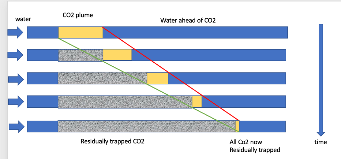
Fig. 10.36 The evolution of CO2 plume length and storage with time.#
Dissolution trapping#
When the CO2 has reached the top of the anticline and ponded, an interface develops between the CO2 and the underlying aquifer water. The CO2 is weakly soluble in water, up to about Csat = 2-3% mass per unit mass, and so we expect that over time the water below the CO2 will become saturated in CO2. If the depth of this water layer below the CO2 is \(H\), then the depth of CO2 dissolved, \(d\), will be given by the mass balance
in terms of the densities of CO2 and water, the depth of the water layer and the saturation concentration.
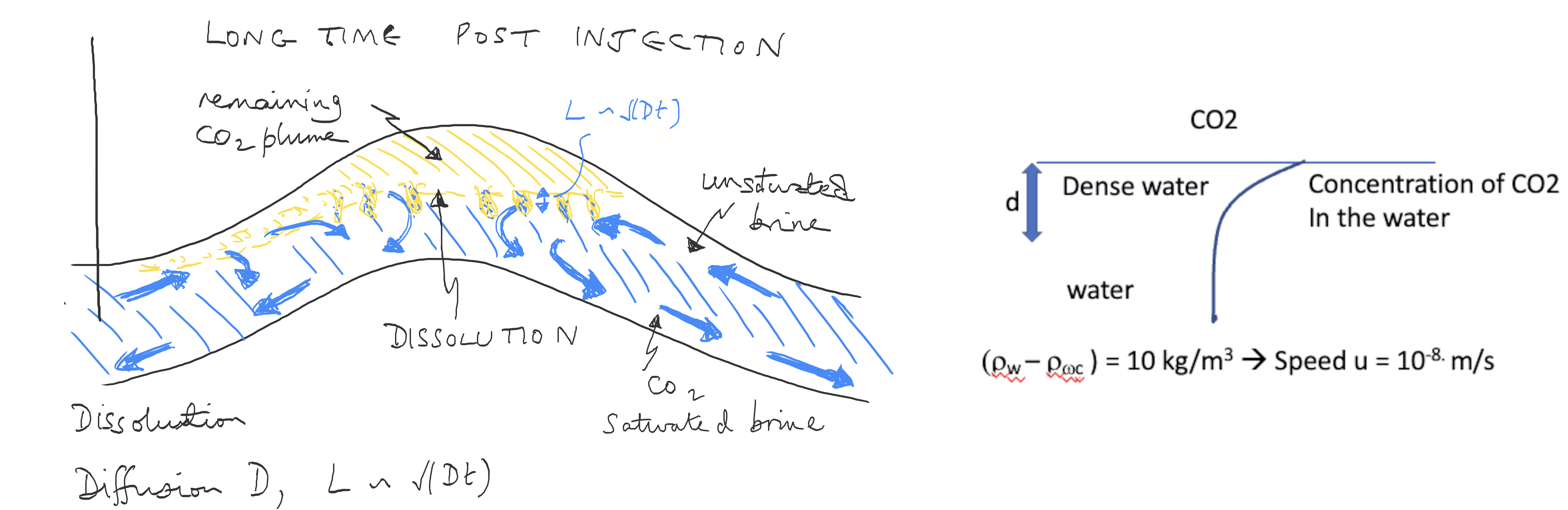
Fig. 10.37 A schematic of dissolution trapping.#
The time required to dissolve the CO2 into the water depends on whether the CO2 moves through the water by molecular diffusion or by convection. The reason the CO2 may mix into the water by convection between the CO2 saturated water and the CO2 unsaturated water is that the density of water increases with concentration of CO2. Hence the water just below the interface with the CO2 layer gradually becomes denser as CO2 diffuses into this water from the CO2 pool above. Suppose that the layer of water into which the CO2 diffuses has reached a thickness d(t) after a time \(t\), then if this layer was to try to sink into the undersaturated water below, it would try to sink as plumes of size \(d\), since this is the characteristic length-scale if the dense water layer.
We now want to establish whether the plume can in fact sink into the layer below. If the plume of dense fluid moves down, it will come into contact with less dense unsaturated fluid, and will try to diffuse CO2 into that water. If the water diffuses out of the plume faster than the plume sinks through the water, then the CO2 concentration of the water in the plume will adjust to that in the surrounding fluid and it will no longer be dense, so it will stop sinking. We can compare the time for the plume to sink a distance \(d\), equal to its own size, with the time to diffuse the CO2 a distance \(d\) and hence to equilibrate the CO2 concentration with the adjacent fluid.
The convection speed is
where in this expression \(\Delta \rho\) is the difference in density between the CO2 saturated water and the unsaturated water below, and so the time to sink a distance \(d\) is \(t_{\mathrm{sink}} = d/U\)
The time to diffuse over the distance \(d\) scales as
where the diffusivity of the CO2 in the water is \(D\).
Hence the convection can persist if
We see from the inequality that for convection we need the plume size
This result shows that the larger the plume, the more likely it is that there is some convection. However, if we consider that the fluid layer has depth \(H\), then the largest plumes cannot be larger than \(H\), the depth of the layer, and so for convection to arise we need
This condition for convection can be re-expressed in the form
And we call this the Rayleigh Darcy number.
Once the water below the CO2 becomes saturated, which happens on a time scale which is either controlled by the convective flow time, \(H/U\), or the diffusion time \(H^2/D\), the dissolution of the CO2 stops until more unsaturated water comes into contact with the CO2 plume. This is a slow process which may be controlled by the slow background hydrological flows of water in the aquifer, and so the remaining CO2 plume may remain for 10’s or 100’s of thousands of years before it dissolves.
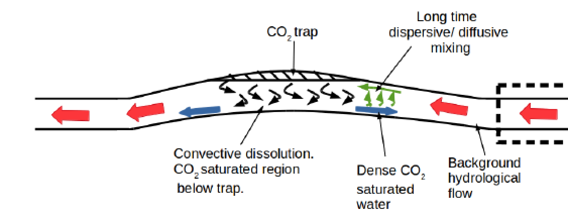
Fig. 10.38 A schematic of CO2 storage.#
We can model this long time dissolution with a box model (!). The flux of CO2 entering the region below the CO2 pool is \(QCo\) where \(Co\) is the background concentration of CO2 and the flux of CO2 leaving this region is \(QC_{sat}\) assuming that the water becomes saturated in CO2 by dissolution faster than the flow time past the pool of CO2. Then the rate of dissolution of CO2 from the pool of CO2 is given in terms of the mass of CO2 dissolving as
and this relation controls how quickly the pool of CO2 dissolves.